
Introduktion
Hydrauliska riktningsventiler fungerar som den primära styrningsmekanismen i mobila och industriella hydraulsystem. Genom att reglera vätskevägens riktning mellan hydraulpumpar, ställdon (cylindrar och hydraulmotorer) och oljebehållare, styr riktningsventilerna maskinens rörelse, hastighet och positioneringsnoggrannhet. I mobila maskiner – som grävmaskiner, jordbrukstraktorer, hjullastare och lastbilskranar – når arbetstrycket rutinmässigt 31,5 MPa (315 bar) med flödeshastigheter på upp till 160 l/min, vilket kräver hög mekanisk precision och hydraulisk effektivitet.
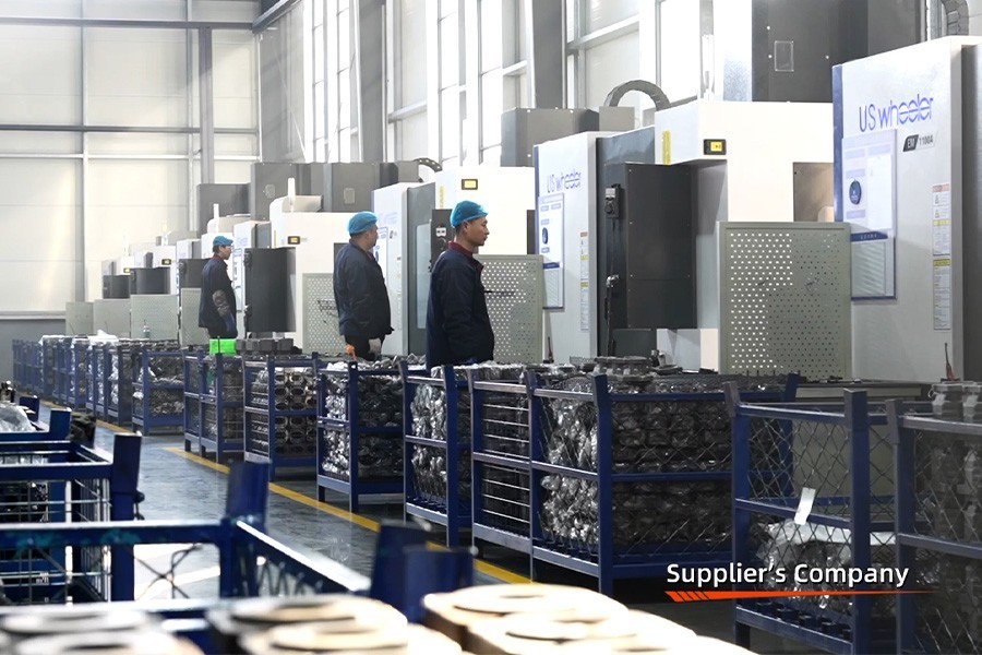
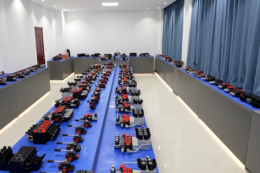
Hos Boxinhuasheng Hydraulic Technology Co., Ltd. representerar teknik för riktningsventiler en av våra kärnkompetenser. Boxinhuasheng, som grundades 2001, har över 25 års erfarenhet av specialiserad ventiltillverkning. Med stöd av 35 seniora hydraulingenjörer producerar vårt produktionscampus på 68 000 m² högpresterande monoblockventiler och sektionsstyrningsventiler certifierade enligt IATF 16949 och SGS revisionsstandarder.
Den här artikeln ger en djupgående teknisk analys av hur riktningsstyrventiler med glidande spol fungerar, detaljerad inre vätskedynamik, konstruktion av spolmätningsskåra, konfigurationer av mittpositioner, aktiveringsmekanismer och viktiga tekniska urvalskriterier för OEM-maskintillverkare.
Grundläggande anatomi för en riktningsstyrventil med glidspol
Medan riktningsventiler kan använda roterande, tallriks- eller checkdesigner, är glidventiler överväldigande föredragna i mobila maskiner på grund av deras kompakta layout, flerspolar staplingsbarhet och överlägsna flödesmätningsmöjligheter.
┌──────────────────────────── ────────────────────────────┐
                  │ ANATOMI ANATOMI FÖR STYRVENTIL RIKTNINGSSPOL │
                  └───────────────────────────┬ ────────────────────────────┘
                                              │
         ┌────────────────────── ────────┬─────┴───────── ───────────────┬─────── ───────────────────────┐
         ▼ ▼ ▼ ▼
┌──────────────────┐ ┌──────────────────┐ ┌──────────────────┐ ┌──────────────────┐
│ Precisionsventil │ │ Slidventil │ │ Intern vätska │ │ Pilot & Main │
│ Gjutkropp │ │ Spole │ │ Portar │ │ Avlastningsventiler │
└──────────────────┘ └──────────────────┘ └──────────────────┘ └──────────────────┘- Precisionsgjuten ventilkropp: Formad av segjärn med hög hållfasthet (QT500-7) för att motstå inre tryckspikar upp till 31,5 MPa utan höljesböjning.
- Glidventilspole: Bearbetad av härdat legerat stål (58-62 HRC), slipat och diamantslipat till ett radiellt spel på 0,006 mm till 0,012 mm inuti ventilhålet.
- Vätskeportar:
- Avlastningsventiler: Integrerade huvudtryckbegränsningsventiler skyddar hydraulsystemet från övertryck.
Driftmekaniken: Steg-för-steg-vätskedirigering
En standard 3-läges, 4-vägs (4/3) riktningsventil illustrerar den grundläggande vätskedirigeringsmekaniken:
+--------------------------------------------------------------------------------+
|                  4/3 RIKTNINGSVENTILSPOLER POSITIONER |
+---------------------+-----------------------------+-----------------------------+
| Spole Position | Vätskeledningsväg | Manöverdonets svar |
+---------------------+-----------------------------+-----------------------------+
| Neutral (mitten) | P ──► T (Öppna Ctr) | Ställdon låst / tryck |
|                     | eller P Blockerad (stängd)| Dumpas till tanken |
| Position 1 (skiftad)| P ──► A , B ──► T | Cylinder förlänger / Motor CW |
| Position 2 (skiftad)| P ──► B , A ──► T | Cylinderindragning / Motor CCW|
+---------------------+-----------------------------+-----------------------------+
#### Neutral position (mitttillstånd)
När manöverspakar eller solenoider är avaktiverade, återför centreringsfjädrar spolen till sitt mittläge:
- Öppet center (tandem / BYPASS): Högtrycksolja som kommer in i P-porten passerar genom ett internt bypass-galleri direkt till T-porten och tillbaka till behållaren under minimalt mottryck. Detta sparar motoreffekt när funktionerna är på tomgång.
- Stängt Center: P-porten är blockerad vid ventilhålet. Används i lastkännande (LS) eller pumpsystem med variabelt deplacement där pumpflödet anpassas automatiskt till systemets behov.
#### Position 1 (Förlänga / Framåt)
Axiell förskjutning av spolen avslöjar interna mätområden:
- Olja frånP-portrinner genom mätskårorna in iArbetsport A, förlänger hydraulcylindern.
- Returolja som kommer ut ur cylindern kommer inArbetsport Boch passerar genom det interna tankgalleriet in iT-port.
#### Position 2 (Tillbaka/bakåt)
Omvänd spolslag skiftar inre vätskebanor:
- Olja frånP-portär riktad tillArbetsport B.
- Returnera vätska frånArbetsport Adränerar tillT-port.
Mätskåror och proportionell flödesreglering
I verkliga mobila maskiner fungerar inte riktningsventiler som enkla binära (ON/OFF) omkopplare; förare kräver exakt, smidig kontroll över cylinderförlängningshastigheten och bomrörelsen.
Att uppnå jämn hastighetsmodulering förlitar sig påspolens mätskåror:
- V-skåror, U-skåror eller triangulära mätslitsar som är slipade in i spolområdena skapar progressiva öppningsområden när spolen rör sig axiellt.
- När en operatör lätt flyttar en kontrollspak passerar vätska genom en smal doseringsöppning, vilket genererar ett kontrollerat tryckfall ($\Delta P$) och levererar proportionellt flöde ($Q = C_d \cdot A(x) \cdot \sqrt{\frac{2\Delta P}{\rho}}$).
- Precisionsprofilslipning av doseringsskåror eliminerar mekaniska stötar och förhindrar plötsliga ryck i lastararmar eller kranbommar under aktivering.
Manövermekanismer: manuella, mekaniska, pneumatiska och elektrohydrauliska
Riktningsventiler kan manövreras med hjälp av flera styringångar beroende på utrustningens arkitektur:
- Manuell spakaktivering: Mekaniska spakar kopplade direkt till spolens bakdel. Direkt mekanisk feedback ger intuitiv förarkänsla på jordbrukstraktorer och mobila maskiner.
- Pneumatisk/kabelfjärrmanövrering: Luftcylindrar eller flexibla push-pull-kablar tillåter montering av ventiler nära ställdon medan kontrollerna finns kvar i fordonshytten.
- Elektrohydraulisk proportionell aktivering: Magnetmanövrerade pilotventiler applicerar hydrauliskt pilottryck (vanligtvis 1,5–3,0 MPa) för att spola ändlock, vilket möjliggör smidig elektronisk styrning via joysticks eller CAN-bus-mikrokontroller.
Manuell spak / kabel ────┐
Pneumatisk pilot ─────┼──► Ventilspoleförskjutning ──► Proportionell flödeseffekt
Elektro-solenoid ─────┘
Tekniska överväganden för val av OEM-ventil
När man specificerar riktningsventiler för nya maskinplattformar måste OEM-designingenjörer utvärdera fyra kritiska vätskedynamiska parametrar:
- Nominellt flöde & maximalt tillåtet tryckfall: Att välja en ventil med otillräcklig flödeskapacitet skapar för hög vätskehastighet, förhöjda oljetemperaturer och parasitiska energiförluster över interna gallerier.
- Tryckklasser och stöttålighet: Ventilerna måste motstå nominella arbetstryck (t.ex. 31,5 MPa) samtidigt som de motstår momentana tryckspikar orsakade av plötsligt lastfall eller skopanslag.
- Läckagefrekvenser för intern spole: Minimering av intern olja som passerar förbi mellan arbetsportar och tankgallerier är avgörande för att förhindra cylinderavdrift när man håller tunga laster i upphöjda lägen.
- Spool-to-Bore Tolerances & Contamination Sensitivity: Extremt snäva spelrum (sub-mikron) minskar internt läckage men ökar känsligheten för vätskekontamination. Att upprätthålla ISO 4406 vätskerenhet (16/14/11) är viktigt.
Slutsats
Hydrauliska riktningsventiler styr vätskedirigering, aktiveringshastighet och driftsäkerhet i mobila maskinapplikationer. Genom exakta spole-till-hål-avstånd som hålls inom 0,002 mm, profilslipade mätskåror och robusta segjärnsgjutgods, producerar Boxinhuasheng Hydraulic Technology Co., Ltd. pålitliga monoblock- och sektionsstyrningsventiler byggda för att tåla tuffa arbetsmiljöer.
Uppbackad av 25+ års tillverkningserfarenhet, 35 seniora ingenjörer, IATF 16949-certifiering och 100 % arbetsbelastningssimuleringstestning över 30+ bänkar, fungerar Boxinhuasheng som en pålitlig OEM-ventiltillverkningspartner.
För tekniska ventilritningar, spolkonfigurationsdiagram eller anpassade grenrörskonsultationer, besökwww.chinesehydraulic.com.